Engineer's Toolbox Visit www.hansarobotics.com

Category Banner

How to Choose the Right Electric Actuator?

Choosing the right electric actuator starts with the job it must perform, not the largest torque number in a catalog. An electric actuator converts electrical power into controlled movement, but applications vary widely. A quarter-turn valve may need precise rotation, while a linear damper may require steady thrust across a longer stroke. The difference matters. An actuator that looks suitable on paper can struggle if its load, travel, or operating schedule has been underestimated. Small details matter.

Begin by defining the motion, load, speed, and accuracy the equipment needs. Check whether the actuator can handle peak torque or thrust, not only the normal operating load. Consider how often it will cycle, how quickly it must move, and what power supply is available at the installation point. Match its enclosure and materials to the actual environment, including dust, moisture, heat, or vibration. Confirm that the mounting pattern, control signals, and position feedback suit the valve or machine. These checks sound basic, yet they are easy to overlook when comparing specifications.

A reliable choice also accounts for maintenance access, manual override, and what should happen during a power failure. Some applications need a defined fail-safe position; others do not. There is no universal best electric actuator, and a specification sheet cannot reveal every site condition. Review the operating requirements with the equipment supplier, then verify key dimensions and performance against the application. A careful selection reduces avoidable problems, though it may still need adjustment after real-world commissioning. That is worth planning for.
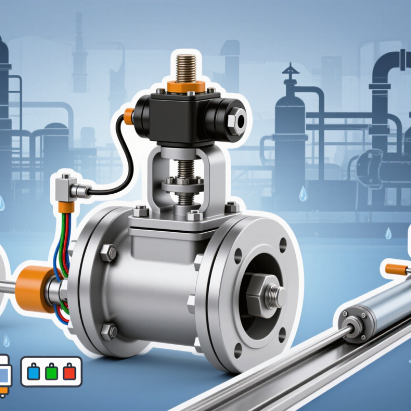
How to Choose the Right Electric Actuator?

Define the Application and Its Operating Requirements

Before comparing electric actuators, describe the job in physical terms. What component will it move, and through what angle or distance? Record the required torque, travel time, and number of operations per hour. Small details matter. A valve that moves easily when new may need more force after its seals age. Measure, don’t guess.

Also note the operating environment. Dust, washdown, vibration, temperature swings, and limited mounting space can all affect actuator performance. Identify the available power supply and control signal, then confirm whether the system needs position feedback or a specific stopping behavior.

What should happen during a power loss?

That answer can shape the actuator type and control arrangement. For a real installation, check the full operating cycle, not just peak torque. Frequent starts may create more heat than occasional movement. Leave a sensible margin for changing conditions, but avoid oversizing without reason; an oversized unit can make positioning less precise.

I have seen specifications miss the awkward part: access for wiring and future adjustment. It is easy to overlook. A clear application brief gives suppliers useful facts and helps engineers compare options on the same basis.
Choose the Actuator Type Based on Motion and Load

How to Choose the Right Electric Actuator?
Choose the Actuator Type Based on Motion and Load

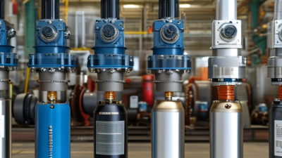
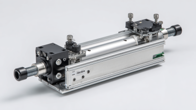
Start with the movement. A linear actuator pushes or pulls along a straight path, such as moving a gate or lifting a small platform. A rotary actuator turns a shaft, valve, or indexing table. Check the required stroke or rotation angle, then measure the load where it acts. A heavy load far from a pivot can demand much more torque than its weight suggests.

Match the actuator’s rated force or torque to the real operating conditions, not just the ideal calculation. Include friction, acceleration, impact, and how often the mechanism cycles. For example, a sliding panel that sticks in cold weather may need extra starting force. The IEA’s Energy Efficiency 2023 report estimates that motor-driven systems use about 53% of global electricity; this figure covers many applications, not actuators alone. It’s a useful reminder to consider energy use alongside motion and load. A neat calculation can still mislead.

Tips: Check the load at its worst position, and confirm duty cycle, speed, and mounting space. Leave a reasonable safety margin, but avoid oversizing without a clear reason.

How to Choose the Right Electric Actuator

Choose the actuator type based on the required motion and the load.

For straight-line lifting, consider a linear actuator and check that its rated force exceeds the load requirement. The chart shows static lifting force calculated as F = m × 9.81 m/s². It excludes friction, acceleration, and any design safety margin. For rotational motion, choose a rotary actuator and size it by the required torque.

Compare Force, Speed, Stroke, and Control Specifications

Force, speed, stroke, and control should be compared against the actual motion, not just a catalog figure. Estimate the load, friction, and any force needed to start moving it. A vertical mechanism also needs to resist gravity when stationary. Leave margin. Check whether the actuator’s rating describes dynamic force, holding force, or both; these are not interchangeable. On a test bench, a sticky guide can demand more force than a clean calculation predicts.

Speed affects more than cycle time. A fast actuator may overshoot a soft stop or make a lightly supported panel vibrate. Match the required travel time to the load, then check whether force changes across the stroke. Stroke length should fit the mechanism’s usable travel, with room for mounting hardware and end limits. Avoid choosing extra travel “just in case” if it creates collision or alignment risks. Even careful estimates miss a little friction.

Control specifications determine how precisely the actuator can behave. A simple on/off input may suit basic end-to-end movement, while adjustable speed or position feedback can help with gradual starts and repeatable stops. Check signal compatibility, limit-switch options, duty cycle, and feedback resolution. Test with the real load if possible; behavior can change after wiring, mounting, and repeated cycles. A useful trial records travel time, stopping position, and motor temperature.

Assess Environmental Conditions and System Compatibility

An electric actuator can perform well on a test bench and struggle after installation. Check the actual environment, not just the room’s average temperature. Heat from nearby equipment can shorten component life, while cold starts may slow movement. Moisture matters. Distinguish occasional splashes from condensation, outdoor rain, or routine washdown. Dust, salt air, and chemical vapors can also affect seals and electrical connections. Vibration from a pump or conveyor may loosen mounts over time. Select an enclosure and materials suited to those conditions, and verify the specified limits against the site’s real operating range. A rating alone does not describe every exposure.

System compatibility deserves the same attention. Compare the actuator’s voltage and control signal with the available supply and controller. Confirm mounting dimensions, shaft or linkage fit, travel, speed, and required torque or thrust. Fit is not enough. A valve may need extra force to break free after sitting idle, so use realistic load data rather than its usual running load. Also check feedback requirements and what happens during a power loss. Heat, load, and frequent cycling can change performance together. It is tempting to oversize for safety, but that can cause poor control or unnecessary wear. Recheck the assumptions with the equipment supplier; site measurements are sometimes incomplete.

How to Choose the Right Electric Actuator? - Assess Environmental Conditions and System Compatibility
Selection Dimension What to Assess Practical Guidance Compatibility Check
Ambient temperature Normal operating temperature, temperature extremes, and heat from nearby equipment. Compare the full expected temperature range with the actuator’s specified operating limits. Consider heaters or insulation where condensation or low temperatures are concerns. Check motor, seals, lubricant, electronics, and cable ratings; the lowest-rated component can limit the usable range.
Ingress protection Exposure to dust, rain, splashing water, temporary immersion, or high-pressure cleaning. Select an enclosure rating suited to the actual exposure. IP ratings distinguish protection against solids and water; an IP rating alone does not establish resistance to corrosion or chemical attack. Verify the rating applies to the complete installed assembly, including connectors, cable entries, covers, and mounting orientation.
Corrosion and chemicals Salt spray, humidity, cleaning agents, process chemicals, and corrosive gases. Confirm material and coating compatibility with the specific substances and concentrations present. A sealed enclosure may still require corrosion-resistant external materials. Check housing, fasteners, output shaft, seals, and conduit fittings; request documented material compatibility where exposure is severe.
Dust and particulates Fine powder, fibers, abrasive particles, and the frequency of airborne dust exposure. Use suitable dust protection and consider particle buildup that could obstruct cooling, moving parts, or manual overrides. Confirm enclosure protection, maintenance access, and any applicable hazardous-area requirements for combustible dust.
Washdown and sanitation Cleaning method, water pressure, temperature, cleaning chemicals, and required hygiene practices. For frequent washdown, verify that the actuator is designed for the cleaning conditions; do not assume that a high ingress rating guarantees washdown suitability. Check surface finish, seals, cable entries, drainage, and whether the actuator’s documentation explicitly permits the intended cleaning process.
Supply voltage and power Available AC or DC supply, voltage tolerance, peak current, and power interruptions. Match the actuator’s rated supply to the system and allow for startup or stall current when sizing the power source. Confirm frequency for AC supplies, polarity for DC supplies, protective devices, grounding, and cable voltage drop.
Required force or torque Load, friction, process pressure, acceleration, and possible jamming or breakaway force. Calculate the required output under the most demanding normal condition. Include an appropriate engineering margin without exceeding the mechanism’s allowable load. Check actuator output across the full stroke or rotation, plus the capacity of the valve, linkage, brackets, and connected structure.
Duty cycle and operating speed Moves per hour, travel time, time under load, and required positioning speed. Compare the application’s operating pattern with the actuator’s rated duty cycle and thermal limits. Frequent cycling can cause overheating even when individual moves are short. Verify speed at the required load, maximum starts per hour, rest periods, and any derating required by ambient temperature.
Control signal and automation system On/off operation, discrete commands, analog positioning, or networked control. Choose an actuator with an input method supported by the control system. Common analog signals include 0–10 V and 4–20 mA, but signal availability varies by model. Check signal type, input impedance or loop requirements, communication protocol, configuration needs, and behavior on signal loss.
Position feedback and limits Whether the system needs end-of-travel indication, continuous position feedback, or both. Use limit switches for discrete endpoint indication or a suitable position sensor for continuous feedback, according to control accuracy requirements. Confirm feedback type, range, resolution, wiring, and compatibility with the controller’s input modules.
Fail-safe behavior Required position during power loss, control failure, or emergency shutdown. Determine whether the mechanism must hold position, move to a defined position, or be manually operated when power is unavailable. Not all electric actuators provide spring-return action. Check backup power or stored-energy options, brake behavior, manual override, and the system’s risk assessment requirements.
Mounting and mechanical interface Available space, shaft or stem geometry, stroke or rotation angle, and installation orientation. Match the actuator’s travel and mounting arrangement to the driven device. Allow room for wiring, ventilation, service, and manual operation. Verify dimensions, coupling, bolt pattern, alignment, allowable side load, and whether an adapter or linkage is required.
Selection note: Confirm all limits against the actuator and driven equipment specifications, then evaluate the complete installed system under its expected operating conditions.

Evaluate Safety, Maintenance, and Lifecycle Costs

How to Choose the Right Electric Actuator?

Evaluate Safety, Maintenance, and Lifecycle Costs

An electric actuator should fit the process, not just the purchase budget. Begin with the real operating conditions: load, travel, duty cycle, temperature, and exposure to dust or moisture. Check how the actuator behaves during a power loss, and confirm that its force and speed suit the equipment it moves. A safety margin matters, but excessive sizing can add cost and wear.

Maintenance access affects both downtime and worker exposure. Look for clear access to terminals, manual overrides, and service points without awkward reaching or dismantling nearby equipment. Ask technicians how often inspections are practical, and whether replacement parts can be changed with ordinary tools. Small details matter. A cramped installation can turn a simple check into a longer shutdown.

Compare lifecycle costs over the expected service period, including energy use, inspections, spare parts, installation, and unplanned downtime. A lower upfront price may not stay lower if seals, batteries, or drive components need frequent attention. For a fair estimate, use your site’s actual duty cycle and maintenance records where available. Estimates are imperfect; revisit them after the first year. The best choice balances dependable operation, manageable maintenance, and costs your team can explain.