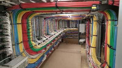
Choosing the right fiber optic cable installation method in 2026 means matching the route to the site, cable, and service demands. Aerial placement can suit existing poles and open corridors, while buried ducts protect cable from weather and many surface hazards. Direct burial may reduce pathway construction, but it requires suitable cable and careful attention to soil conditions. In dense streets, microtrenching can offer a compact route, though access, restoration, and local site requirements need close review. There is no universal winner.
Good installation begins before the first pull. Teams should review route drawings, manufacturer limits, bend radius, pulling tension, access points, and expected future maintenance. On site, clean connectors, secure closures, and well-managed slack help protect signal quality. Small details matter. A single sharp bend can undermine an otherwise tidy job. After placement, appropriate inspection and testing, such as optical loss measurements and OTDR checks, can help identify problems before handover. Test results should be recorded clearly, not simply filed away.
This guide compares common installation methods, their practical strengths, and the trade-offs that project planners should consider. It also looks at indoor pathways, weather exposure, traffic disruption, labor needs, and long-term repair access. Real sites rarely match drawings perfectly; a route may cross an unexpected obstruction or leave too little room at a handhole. That is worth admitting. Careful surveys, qualified technicians, and documented procedures make decisions more reliable, but they cannot remove every uncertainty. The best method is the one that meets performance needs while remaining safe, maintainable, and suited to the actual site.
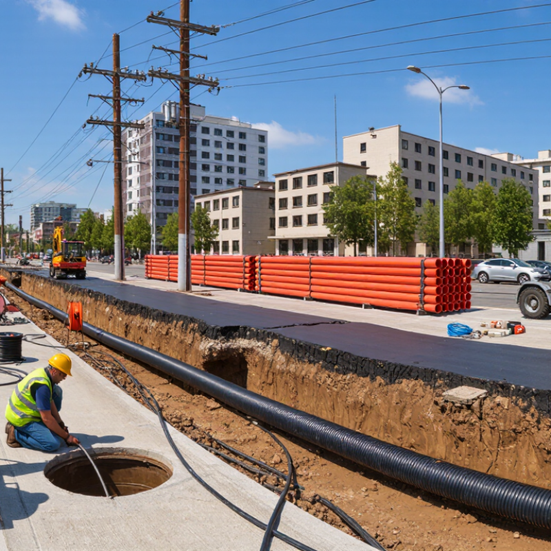
Map the route before choosing the build.
Mark poles, road crossings, tree roots, utility entries, and the building’s fiber termination point. Aerial cable can suit open corridors with existing poles, but wind, ice, and branches add exposure. Duct installation protects cable from surface damage and allows future replacement, though blocked conduits can delay work. Direct burial avoids poles and ducts; rocky soil and later excavation make it less forgiving. Indoor runs need protected pathways, tidy bends, and clear separation from heat sources. Small details matter.
Check soil, access, drainage, permits, and maintenance needs on site—not only on a map. The Fiber Optic Association’s installation guidance gives a common bend-radius rule: about 20 cable diameters while pulling and 10 after placement. Follow the cable specification if it requires more. ITU-T Recommendation L.156 also emphasizes installation conditions and mechanical stress. Keep slack. Leave accessible service loops near handholes and equipment, but never coil cable tightly.
A short route may still be a poor choice if crews cannot reach a blocked duct or damaged span. I would recheck the route after heavy rain; drainage assumptions are easy to get wrong.

Choose fiber-optic cable by matching its mechanical test evidence to the route, not by relying on a generic “rugged” label. IEC 60794-1-21 describes mechanical test methods, not a universal installation recipe. E1 evaluates tensile performance, relevant when a cable is pulled through a long duct. E3 assesses crushing, which matters beneath trays or at crowded entry points. E4 examines impact resistance. Match the evidence to the route.
For repeated bends or twisting during placement, review applicable bending and torsion tests, such as E6 and E7. A drawing rarely captures every snag or awkward hand movement. That uncertainty matters. Check the cable’s test report for its construction, test conditions, applied load, and acceptance limits; results from one design may not represent another. For aerial spans, ducts, or tight indoor pathways, combine suitable test data with the installation limits in the cable documentation. Use rollers, respect the specified bend radius, and avoid pulling beyond the stated tension. Even a strong test result cannot excuse poor handling. A brief site review can reveal practical risks that paperwork misses.
Before routing fiber, check the cable’s outside diameter (OD) and the manufacturer’s bend-radius limits. A common guideline is 20× OD while the cable is moving and 10× OD after installation. These are not universal limits; the datasheet takes priority. For a 6 mm cable, that means 120 mm dynamic and 60 mm static. Bend radius refers to the curve’s radius, not its full width. Confirm how the datasheet defines the measurement.
During pulling, maintain the larger dynamic radius through corners, trays, and entry points. A smooth sweep is safer than a sharp turn around a cabinet edge. Watch the cable as it passes over rollers; a brief pinch can leave damage that is hard to spot. Pulling tension matters too, so stay within the specified limit. Looks tidy. Still risky.
Once the cable is secured and stationary, the static limit may apply, but avoid tight ties that flatten the jacket. Leave slack in broad loops, not small coils. Check the route again after closing panels, since a door or cover can press against the cable. These details are easy to miss, especially when space is tight; a neat installation can still violate the datasheet.
A fiber route is only reliable when its clearances and cover depth match local requirements.
For aerial runs, check the required distance above roads, driveways, and pedestrian areas. Account for cable sag, pole spacing, and seasonal movement, not just the height measured on installation day. Keep the route clear of power conductors and follow the applicable separation rules.
Small details matter. A cable that looks safely placed in mild weather may hang lower when conditions change. Confirm measurements with the local authority and utility owners before work begins.
Buried runs need equal care.
Required cover can vary with soil, conduit, surface type, and crossings, so do not rely on a depth remembered from another job. Check local codes and permit conditions, then mark the route and arrange utility locating before excavation. At road edges and driveways, note where cover may be reduced by grading or later repairs.
Record the installed route and measured depth; this helps prevent accidental damage during future work.
A plan can look tidy on paper and still miss an awkward crossing. Recheck the actual site, and revise the route when conditions differ.
A clean installation can still lose light. Verify the installed link with procedures suited to its fiber type, rather than relying on a visual inspection or equipment estimate. IEC 61280-4-1 covers installed multimode cabling measurements; IEC 61280-4-2 covers single-mode cabling. Keep the test method, reference setup, and recorded wavelength consistent across the link.
For multimode fiber, test at the specified wavelengths, commonly 850 nm and 1300 nm, and use a launch condition that controls how light enters the fiber. Encircled-flux-compliant launch conditions help make results repeatable. Small setup differences matter. For single-mode links, measurements commonly use 1310 nm and 1550 nm. Inspect and clean connector end faces before testing; one speck of dust can distort a result. Set a valid reference, then measure both directions when the procedure calls for it. Record wavelength, reference method, test-cord details, and measured loss with each result. Field work is rarely perfect: tight bends, awkward panels, and rushed reconnections can affect readings. If a value looks inconsistent, repeat the setup and measurement before accepting it.
2026 Best Fiber Optic Cable Installation Methods? — Verify Loss with IEC 61280-4-1 Multimode and 4-2 Single-Mode Test Methods
| Installation method | Typical application | Installation controls | Post-installation verification | Applicable loss-test method |
|---|---|---|---|---|
| Conduit or duct pull | Building pathways, campus routes, and underground ducts with an accessible continuous pathway. | Confirm duct capacity and route condition; use an approved pulling grip or swivel where appropriate. Keep pulling tension and bend radius within the cable manufacturer’s limits, and avoid twists or kinks. | Inspect accessible cable sections and closures. Test each fiber end-to-end for insertion loss after connectors and splices are complete. | IEC 61280-4-1 for multimode cabling; IEC 61280-4-2 for single-mode cabling. |
| Cable tray or ladder rack | Indoor backbone routes in equipment rooms, risers, and service corridors. | Support the cable at suitable intervals; avoid crushing, sharp edges, tight bends, and overfilled pathways. Observe the cable’s specified bend radius and installation tension. | Check for visible damage and stressed transitions at tray exits, cabinets, and closures. Perform end-to-end loss testing on every installed fiber. | Use the IEC method matching the fiber type. Multimode tests commonly use 850 nm and 1300 nm; single-mode tests commonly use 1310 nm and 1550 nm. |
| Direct-buried cable | Outdoor routes designed for burial where duct is not used. | Use cable rated for the burial environment. Follow the route design for depth, separation, warning markers, and protection at crossings; avoid excessive pulling force and sharp bends. | Test the completed link after splicing and termination. Record results by fiber and direction, and compare measured loss with the project’s engineered loss budget. | IEC 61280-4-1 for multimode links or IEC 61280-4-2 for single-mode links, as applicable. |
| Aerial installation | Outdoor routes on poles or other approved support structures. | Select cable and support hardware rated for the route. Maintain specified sag, tension, clearance, and bend radius; protect the cable at attachment points and transitions. | Inspect support points and building entries, then measure end-to-end insertion loss after the link is terminated. Investigate unexpected loss before acceptance. | Apply the relevant IEC installed-cabling attenuation method for the multimode or single-mode fiber under test. |
| Microduct with blown fiber | Campus and access networks designed for small ducts and future fiber additions. | Verify duct continuity and route suitability before blowing. Follow cable and equipment limits for air pressure, blowing force, bend radius, and installation distance. | Check the installed cable path and terminations. Clean and inspect connector end faces, then test insertion loss across each completed fiber link. | IEC 61280-4-1 for multimode; IEC 61280-4-2 for single-mode. Use launch conditions suitable for the fiber type. |
| Indoor surface or raceway routing | Retrofits and short routes where existing pathways are unavailable or impractical. | Use cable and raceway appropriate to the building environment. Protect the route from impact, compression, sharp corners, and unauthorized disturbance. | Inspect the full accessible route and termination points. Measure link loss after installation and document the test setup and results. | Use the corresponding IEC 61280-4-1 or IEC 61280-4-2 method according to whether the installed link is multimode or single-mode. |
| Common acceptance workflow | Applies to completed installed links, regardless of pathway method. | Identify fiber type and link endpoints. Inspect and clean mating surfaces before testing; establish the reference and test configuration in accordance with the applicable procedure. | Use an optical loss test set to measure end-to-end insertion loss at the relevant wavelengths. Record fiber ID, wavelength, direction, reference method, and measured result. Compare results with the project specification and calculated loss budget. | IEC 61280-4-1: installed multimode cabling plant attenuation measurement. IEC 61280-4-2: installed single-mode cabling plant attenuation measurement. |
Acceptance note: There is no single loss limit that applies to every fiber link. Set pass/fail limits from the link design, component specifications, applicable standards, and project requirements. Follow the cable manufacturer’s limits for bend radius and pulling tension; these vary by cable construction and installation condition.