What Are the Top Types of Worm Gears?
Worm Gears turn motion through a compact, usually right-angle drive. Their defining pair is a screw-like worm and a toothed wheel. This layout can deliver high reduction in a small space, making it useful in conveyors, lifting equipment, and positioning systems. Yet the label “worm gear” covers several designs, and they do not behave identically.
Gear-design authority Darle W. Dudley, author of Handbook of Practical Gear Design, provides a useful foundation for comparing them. A concise editorial takeaway from his design approach—not a verbatim quotation—is: “Choose by operating duty, not by label.” That distinction matters when comparing single-enveloping, double-enveloping, cylindrical, and duplex worm gears. Each brings different trade-offs in contact area, adjustment, load capacity, and manufacturing complexity.
Small details matter. A warm gearbox casing, a thin film of lubricant, or measurable backlash can reveal more than a catalog description. A high reduction ratio may sound ideal, but efficiency, heat, speed, and duty cycle still shape the right choice. Even a well-made gear set can disappoint if its lubrication or alignment is wrong. That part is easy to underestimate.
This guide compares the top types of Worm Gears, explains how their geometry affects performance, and identifies where each design fits best. It also flags practical limits, because no single type suits every machine. The goal is a clearer selection process, not a perfect-sounding answer.
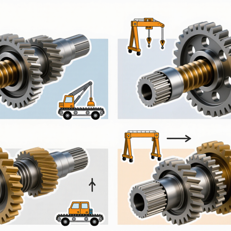
How Worm Gear Types Are Classified
Worm gears are classified by geometry, tooth profile, and the number of worm starts. These categories describe how the parts engage, not just their appearance. ISO 10828:2020 covers worm profiles and gear-mesh geometry, giving engineers a consistent basis for describing and checking designs. A common distinction is cylindrical versus globoid geometry. In a single-enveloping set, the worm contacts the wheel; a double-enveloping design wraps around both members. More contact can support higher load capacity, but alignment and lubrication become especially important.
Start count also changes the ratio. A 40-tooth wheel driven by a two-start worm gives a nominal 20:1 ratio: wheel teeth divided by worm starts. ANSI/AGMA 6022-C93, the Design Manual for Cylindrical Wormgearing, provides an industry reference for evaluating cylindrical worm designs. Still, a ratio alone cannot predict performance. Lead angle, materials, surface finish, and operating temperature matter. Labels can overlap in product descriptions, so check the actual drawing or specification.
Tips: Confirm the gear geometry and worm-start count before comparing units. Then review the stated load, speed, lubricant, and test conditions. Small details matter. A catalog value without its test setup may be less useful than it looks.
What Are the Top Types of Worm Gears? - How Worm Gear Types Are Classified
| Type or Classification | How It Is Classified | Key Characteristics | Typical Advantages | Common Considerations |
| Cylindrical worm gear set | The worm has a cylindrical body and engages a worm wheel on crossed, usually perpendicular, shafts. | A widely used geometry. The wheel teeth are commonly shaped to partially wrap around the worm. | Compact layout, substantial speed reduction in one stage, and smooth operation when correctly designed and lubricated. | Sliding contact creates friction and heat; performance depends on materials, lubrication, speed, and load. |
| Non-enveloping set | Neither the worm nor the wheel is shaped to wrap around the other. | Contact is generally more localized than in enveloping designs. | Relatively straightforward geometry and manufacturing. | Contact area and load capacity may be more limited than in comparable enveloping designs. |
| Single-enveloping set | The worm wheel has a concave, throated tooth form that partially wraps around a cylindrical worm. | Often called a throated-wheel arrangement; it is a common worm gear configuration. | Greater contact area than a non-enveloping set of similar size can support load transmission in a compact package. | Requires suitable alignment and lubrication; sliding losses and heat remain important design factors. |
| Double-enveloping set | Both members are shaped to wrap around one another; it commonly uses a globoidal worm and a throated wheel. | The mating surfaces can provide a comparatively large contact area. | Can transmit high loads in a compact design when properly engineered. | More demanding to manufacture and align; suitability depends on the application and operating conditions. |
| Globoidal worm arrangement | The worm body narrows near its middle and widens toward its ends, rather than remaining cylindrical. | Typically associated with double-enveloping designs; the geometry is intended to mesh with a specially shaped wheel. | Can provide extensive tooth contact in a correctly matched gear set. | Needs carefully matched geometry, accurate setup, and appropriate lubrication. |
Classification note: These categories describe different aspects of worm gearing and can overlap. For example, a cylindrical worm with a throated wheel is a single-enveloping set, while a globoidal worm is commonly used in a double-enveloping set.
Cylindrical Worm Gears
Cylindrical worm gears use a screw-shaped worm to drive a toothed wheel, usually on shafts set at right angles. The worm has a cylindrical body, unlike globoid designs that wrap more closely around the wheel. This straightforward geometry suits compact drives needing substantial speed reduction in one stage. Quiet operation is another practical advantage.
The contact is mostly sliding, not rolling. That detail shapes performance. A typical assembly pairs a hardened steel worm with a bronze wheel, though material choice depends on load, speed, and lubrication. Sliding contact can generate heat and reduce efficiency, especially at higher speeds. A suitable lubricant, accurate alignment, and a sound housing help control wear. Check operating temperature during commissioning; a gearbox that feels warm may be normal, but a rising temperature needs investigation.
Cylindrical worm gears can resist back-driving, but they are not automatically self-locking. Lead angle, friction, lubrication, and vibration all affect whether the output can turn the worm. Do not rely on that behavior alone to hold a suspended load. Tooth contact also needs attention: uneven marks across the wheel may indicate misalignment or incorrect mounting distance. Small setup errors matter. Even a well-made gear set can run poorly when installation is careless.
Cylindrical Worm Gears: Common Profiles and Reduction Ratios
Common cylindrical worm profiles include Archimedean (ZA), normal (ZN), involute (ZI), and convolute (ZK). The chart shows how the number of worm starts affects the theoretical reduction ratio for a 40-tooth wheel.
Illustrative calculations, not performance ratings. Reduction ratio = wheel teeth ÷ worm starts; actual gear selection also depends on factors such as load, efficiency, materials, and lubrication.
Single- and Double-Enveloping Worm Gears
What Are the Top Types of Worm Gears?
Single- and Double-Enveloping Worm Gears
Single-enveloping worm gears pair a cylindrical worm with a wheel whose teeth curve around it. That curved profile creates more contact than a simple, flat-sided mesh. The larger contact area can help distribute load and support smoother operation. Yet the benefit depends on accurate alignment, suitable materials, and steady lubrication. A small setup error can concentrate wear on just a few teeth.
Double-enveloping designs curve around both members. The worm is hourglass-shaped, while the wheel teeth also wrap around the worm. This geometry can provide a broader contact area and carry substantial loads in a compact assembly. It is not magic. Manufacturing and alignment are more demanding, and sliding contact can generate heat. Lubricant choice and operating speed matter.
The practical choice depends on the job, not a gear’s label. Consider required torque, available space, duty cycle, maintenance access, and allowable heat. A quick visual check can show the geometry, but it cannot confirm capacity or service life. Those require engineering data and operating conditions. It is tempting to assume more contact always means a better drive; that is an oversimplification worth questioning. A carefully specified single-enveloping set may suit an application better than a more complex double-enveloping one.
Globoid (Hourglass) Worm Gears
Among the main worm gear designs, the globoid type is distinctive for its hourglass-shaped worm. Its profile curves around the worm wheel instead of remaining straight-sided. This enveloping geometry can bring several teeth into contact at once. The result may be higher load capacity and smoother transmission in a compact space.
In operation, the curved worm and wheel need careful alignment. A small mounting error can shift the contact pattern toward a tooth edge, raising stress and wear. Manufacturing is also more demanding than for a simple cylindrical worm set. The larger contact area does not guarantee better efficiency; sliding friction and lubrication still matter. That is not automatic. Engineers should check speed, torque, operating temperature, and available lubricant before choosing this design. A practical inspection looks for an even contact mark across the tooth face, not a narrow stripe at one edge.
Tips: Confirm the specified center distance and alignment during assembly. Apply the lubricant recommended for the operating conditions, then inspect for uneven wear after a controlled run-in. If the mesh runs hot, stop and investigate rather than assuming the gear will settle.
Duplex Worm Gears
Duplex worm gears use a worm with changing tooth thickness along its axis. Moving the worm axially changes the clearance between its teeth and the wheel, allowing backlash adjustment without replacing either part. This is useful in indexing tables, rotary stages, and compact positioning drives, where a small amount of lost motion can affect repeatability. Fine adjustment matters.
The adjustment is not a cure-all. Excessive preload can raise friction, heat, and wear; lubricant condition and mounting alignment still matter. ISO/TR 14521:2010 provides calculation methods for worm-gear load capacity, while backlash and operating temperature should be checked in the actual assembly.
The U.S. Department of Energy’s Improving Motor and Drive System Performance sourcebook reports that motor-driven systems account for about 68% of electricity use in U.S. manufacturing. That figure covers many drive types, not worm gears alone, but it shows why transmission losses deserve attention.
A practical inspection should record backlash at several wheel positions, then repeat the measurement after the drive reaches operating temperature. Small differences can be revealing.