7 Tips for Choosing a Threaded Linear Shaft
Choosing a Threaded Linear Shaft starts with understanding how it will move, carry load, and connect to the rest of your assembly. A shaft that looks suitable on a drawing may perform poorly if its thread, support, or alignment does not match the application. Small details matter. A few millimeters of unsupported length can affect deflection, while an incompatible thread pitch can make installation difficult.
Before comparing products, define the required travel, load, speed, and operating environment. Then check shaft diameter, thread form and pitch, material, surface finish, straightness, and dimensional tolerances. These specifications influence strength, wear, positioning accuracy, and compatibility with nuts, bearings, and couplings. For example, a dusty workshop may call for different protection and maintenance than a clean assembly area. Confirm critical dimensions against the supplier’s drawing or datasheet, rather than relying on appearance alone.
This guide presents seven practical tips for making a more informed choice. It covers load capacity, material selection, thread compatibility, accuracy, support, environmental conditions, and supplier documentation. No single specification guarantees good performance. Installation, lubrication, and alignment also matter, and these details are easy to underestimate. Measure twice. If the application has unusual loads or tight positioning requirements, verify the design with a qualified engineer or the manufacturer before ordering.
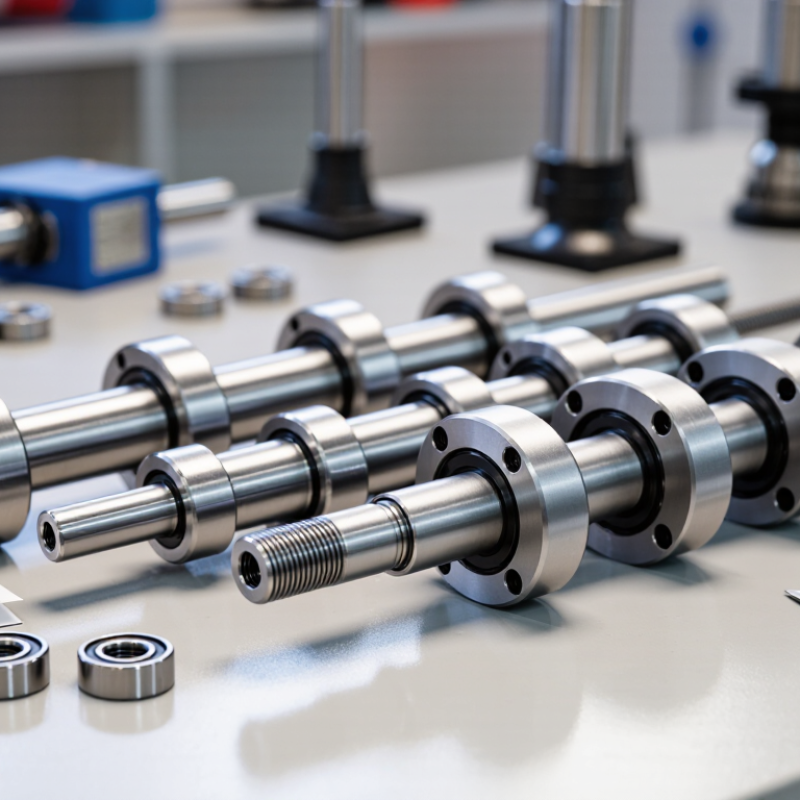
Identify the Shaft’s Function and Motion Requirements
Start by defining what the shaft must do in the assembly. Will it rotate inside a stationary nut, or travel linearly while the nut remains fixed? That distinction affects how the shaft is supported and how motion is transmitted. Write down the required stroke, direction, speed, and positioning accuracy. Small details matter. A carriage moving 300 millimeters several times a minute has different needs from a shaft that adjusts a position once per shift.
Next, identify the forces and operating pattern. Note the axial load, any side load, how often the mechanism starts and stops, and whether it runs continuously. Side load can cause deflection or uneven wear, so avoid treating the shaft as a simple push-pull part. Thread pitch also matters: a finer pitch can provide smaller movement per revolution, but may require more turns. Measure twice. Then check available space, end support, and alignment with the mating nut. A slight misalignment can create binding, even when the shaft looks straight on the bench. It is tempting to choose by diameter first; I would verify the motion requirements before settling on a size. If load or accuracy figures are uncertain, record that uncertainty and test the assembly under realistic conditions.
Calculate Loads, Speed, and Required Precision
Before selecting a threaded linear shaft, calculate the load it must carry. Include the moving carriage, workpiece, fixtures, and any force from cutting or pushing. A 12-kilogram assembly weighs about 118 newtons, but acceleration can raise the force the drive must handle. Check axial load, side load, and bending moment separately; a shaft may tolerate one while struggling with another. Measure it twice. Also check shaft deflection and buckling for the unsupported length, especially when the shaft is slender or mounted at one end. Real installations rarely match a neat diagram.
Speed depends on more than the motor’s rated revolutions per minute. Shaft lead determines travel per revolution, while length, diameter, and support conditions affect vibration and critical speed. Compare the required travel rate with the shaft’s safe operating range, then allow margin for acceleration and changing loads. Don’t ignore duty cycle. A shaft that runs briefly may heat differently from one moving all day.
Set precision from the actual task: positioning a sensor differs from guiding a cutting tool. Account for lead error, backlash, bearing play, frame stiffness, and thermal expansion. A dial indicator can reveal movement that a catalog tolerance does not explain. That matters. I’d also review the complete assembly, not just the shaft specification, and test under representative load. One assumption may still be off; document it and revisit the calculation after a trial run.
Select Shaft Dimensions and Thread Specifications
Choose shaft dimensions from the machine’s actual travel and support layout, not from the available space alone. Measure the required stroke, bearing spacing, and end allowances. Then select a diameter that can handle the load without excessive deflection. Check the unsupported span; a long, slender shaft may bend even when its nominal load rating seems adequate. Small details matter.
Specify the thread diameter, pitch, hand, and tolerance class. Pitch is the distance between adjacent thread crests; for a single-start thread, it also equals the lead. Confirm whether threads are needed along the full shaft or only at the ends. Match the thread to the mating nut or component, and provide enough engagement to resist loosening under expected vibration. Do not rely on a nominal diameter alone.
A frequent specification gap is the transition between the threaded section and the bearing surface. State shoulder locations, usable thread length, and any required relief or chamfer. Check that the shaft’s straightness and bearing-fit tolerances suit the application. A caliper can verify basic diameter, but a thread-pitch gauge helps confirm pitch. If fit is critical, review a sample assembly before ordering a full batch; drawings can still leave room for interpretation.
7 Tips for Choosing a Threaded Linear Shaft — Select Shaft Dimensions and Thread Specifications
Compare common ISO metric coarse-thread sizes when selecting a threaded shaft. The chart shows nominal thread diameter and its corresponding pitch.
How to use this chart: Thread pitch is the distance between adjacent thread crests. Choose a diameter and pitch that suit the mating component, load, and installation requirements; also verify the required thread tolerance and shaft dimensions with the component specifications.
Choose Materials and Surface Treatments for the Environment
A threaded linear shaft may look simple, but its surroundings can decide how long it runs smoothly. Start by checking moisture, dust, cleaning routines, and temperature changes. A shaft near a wash station faces a different risk from one inside a dry, guarded machine. Rust starts quietly.
Choose the base material to match those conditions and the shaft’s load. Stainless steel can resist many forms of corrosion, but it is not immune to every chemical or cleaning agent. Carbon or alloy steel may suit dry, protected equipment and offer useful strength, though exposed surfaces need protection. Check compatibility with nearby components, too; dissimilar metals and trapped moisture can create problems. It is easy to over-specify a material when a simple protective design might work better.
Surface treatment matters at the threads and along the bearing path. A coating can improve wear or corrosion resistance, but its thickness may affect clearances and fit. Ask how the finish holds up under actual contact, not just in a catalog description. For dusty sites, consider whether grit can collect in the thread roots. For humid areas, inspect edges and damaged spots where protection may be thin. Check the whole assembly. Confirm lubrication, seals, and cleaning methods together, then set an inspection interval that reflects real operating conditions.
Verify Compatibility, Quality, and Supplier Support
A threaded linear shaft can match a drawing and still bind in the assembly. Check the thread diameter, pitch, lead, and hand against the mating nut, then confirm travel length and end geometry. A small pitch mismatch can cause rough movement or premature wear. Check the material and finish, too: a shaft exposed to moisture may need corrosion-resistant protection, while a coating can change its effective diameter. Easy to overlook.
Supplier support matters when dimensions are nonstandard or operating conditions are unclear. Ask for tolerance data, material details, inspection records, and guidance on lubrication and alignment. Deloitte’s 2024 Smart Manufacturing Survey found that 92% of surveyed manufacturers expected smart manufacturing to be a primary driver of competitiveness within three years. That makes traceable specifications and reliable quality information increasingly useful—not just paperwork. Still, a report cannot verify a particular shaft; inspect the part and test it in its actual application.
Before ordering, confirm stock status, lead time, packaging, and how the supplier handles dimensional questions or defects. Request a sample when fit is critical. Check that the drawing uses the same units and datum references as your design. I would not assume “standard” means interchangeable. One overlooked detail can send the assembly back to the bench.