

Engineer's Toolbox
Visit www.hansarobotics.com

Choosing Automotive Oscillators in 2026 means looking beyond frequency and price. These timing components help coordinate engine controllers, driver-assistance sensors, vehicle networks, and infotainment systems. A small timing error can become a larger integration problem. Details matter.
The market context is changing quickly. OICA reported 93.5 million motor vehicles produced worldwide in 2023, while the International Energy Agency’s Global EV Outlook 2024 projected electric-car sales would reach about 17 million that year. More electronic systems and faster vehicle networks increase the need for dependable clock signals. They also make component selection less forgiving.
Engineers should compare frequency stability across temperature, supply-voltage sensitivity, startup time, aging, vibration tolerance, and electromagnetic compatibility. Check the actual operating profile, not only the headline specification. A crystal oscillator suitable for a cabin display may not meet the demands of a powertrain controller or an exposed sensor module. That distinction is easy to miss.
Automotive qualification deserves close attention. AEC-Q200 testing can provide useful evidence of component robustness, but it does not, by itself, establish functional safety or guarantee performance in every vehicle design. Review test conditions, traceability, lifecycle support, and supplier change controls. Ask for data.
In the sections ahead, this guide explains how to match oscillator technology and specifications to application needs, compare supplier evidence, and avoid common selection traps. Some trade-offs remain imperfect: tighter stability may cost more or consume additional power. The right choice is the one supported by measured requirements, credible documentation, and validation in the intended system.
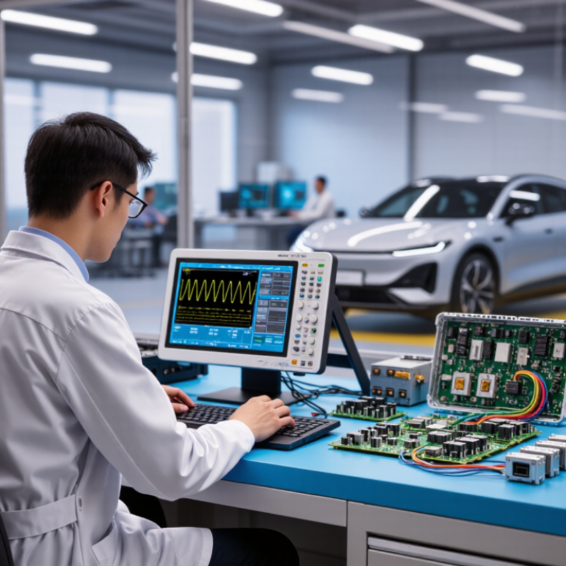
How to Choose Automotive Oscillators in 2026
Define the Role of Oscillators in Automotive Systems
An automotive oscillator generates a repeating clock signal that helps electronic systems keep time. Engine controllers use that timing to coordinate sensor readings and control actions. Communication modules rely on it to move data at predictable intervals. In a dashboard display, it helps keep processing and updates in sync. The oscillator does not make decisions; it provides the timing reference that other components depend on.
Timing matters. A small frequency shift can affect when signals arrive or how reliably two modules communicate. Temperature changes under the hood, vibration, and power-supply variation can all influence performance. The relevant limits depend on the system’s role: a safety-related controller may have different timing needs from a convenience feature. It is easy to focus only on nominal frequency. That can miss startup behavior, jitter, or long-term stability. Bench testing helps, but it may not fully reflect conditions inside a vehicle.
Tips: Start with the required frequency, operating temperature range, startup time, and stability limits. Check the oscillator’s vibration and electromagnetic compatibility data, then verify performance on the actual circuit board. If the system requirements are still unclear, pause before choosing a part; that uncertainty deserves review.
| Automotive System | Role of the Oscillator | Illustrative Reference Frequencies | Key Selection Considerations | Design Verification |
|---|---|---|---|---|
| Vehicle control units and microcontrollers | Provides a stable clock reference for processor execution, timers, and peripheral interfaces. | Common design examples include 8, 16, 20, and 25 MHz; the required value is set by the controller and system design. | Check the controller’s supported clock inputs, frequency tolerance, startup time, supply voltage, and operating-temperature range. | Confirm clock accuracy and startup behavior across the intended voltage and temperature conditions. |
| CAN and LIN communication modules | Supports timing for the controller or communication interface that generates and samples bus signals. | Frequency depends on the selected controller and its clock architecture; there is no single oscillator frequency for either bus. | Assess timing accuracy, jitter, and clock-source requirements against the communication device data sheet and network design. | Verify bit timing and communication operation over the vehicle’s required operating conditions. |
| Automotive Ethernet interfaces | Supplies or helps derive a reference clock for the Ethernet PHY, switch, or associated processor. | 25 MHz and 50 MHz are examples used by some Ethernet devices; the required reference is device-specific. | Check the PHY or switch data sheet for reference frequency, input format, tolerance, jitter, and clock-output requirements. | Validate link establishment and operation with the intended PHY, layout, and clock distribution network. |
| GNSS and positioning modules | Provides a frequency reference used by receiver timing and signal-processing circuits. | Reference frequencies vary by receiver design; use the frequency specified for the chosen module or chipset. | Evaluate frequency stability, phase noise, temperature behavior, and any requirements for synchronization or holdover. | Check positioning performance and reference-clock behavior during temperature changes and startup. |
| Radar and sensing electronics | Clocks digital processing and supporting interfaces; radar transmit-frequency generation is handled by the RF synthesizer, not by the reference oscillator alone. | Reference-clock examples such as 20 or 40 MHz may appear in particular designs; they are not universal radar requirements. | Follow the radar chipset’s reference-clock specifications, including phase noise, jitter, frequency accuracy, and thermal stability. | Confirm timing and RF performance using the chipset requirements and the complete system design. |
| Infotainment and display controllers | Provides a clock reference for processors, audio interfaces, storage, or display-related circuitry. | Frequencies are determined by the selected processor and interface; multiple clock domains may be required. | Consider frequency synthesis needs, output count, electromagnetic compatibility, power consumption, and clock-tree layout. | Check interface timing, signal integrity, and conducted or radiated emissions in the assembled system. |
| Body electronics and power-management controllers | Supports timekeeping, control loops, and communication functions where a stable external clock is required. | Use the frequency and accuracy specified by the controller; some devices can use an internal clock for selected functions. | Compare external-clock accuracy with the application’s timing needs, standby-current budget, and available internal-clock options. | Verify performance in normal operation, low-power modes, and transitions between operating states. |
| Selection across all automotive applications | Acts as a timing reference; the oscillator does not by itself define the complete system’s timing performance. | Select only from frequencies and clock formats supported by the receiving device. | Match operating temperature to the actual use case. Common automotive component ranges include −40 to +105 °C, −40 to +125 °C, and, where required, −40 to +150 °C. | Review component qualification and reliability evidence against applicable customer and industry requirements. AEC qualification requirements depend on component type and program; do not assume one qualification applies to every oscillator. |
Note: Frequencies shown are illustrative design examples, not universal automotive standards. Confirm the required frequency, tolerance, jitter, phase noise, output type, temperature range, and qualification requirements in the receiving device data sheet and vehicle-program specifications.